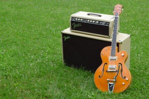
 If you’ve followed my blog, you’ll know that I recently purchased a 1963 Fender Bassman amp (6G6-B). Old amps like this often need a lot of work to make them playable, but what attracted me to this one was the fact that the work had already been done. The problem, I would soon discover, was that the work had not been done correctly, or with quality parts.
That’s not to say that the seller was dishonest. The amp worked, and it worked well, but it did not deliver the stellar tone that these amps are famous for. Since I have a soldering iron, and I’m not afraid to use it, I set out on a quest to make a great amp even better.
For all you tone-chasing guitarists out there, the amp sounded like a vintage Fender, but it had way too much headroom, and call me old, but it was way too loud. Having never owned one of these amps before, I thought that it was just par for the course, but in speaking with Tavo Vega, we came to the conclusion that something wasn’t right. And by “we”, I mean “he”. When I told him that his Brain Selzer preamp pedal made my already loud amp even louder, he replied that there had to be something wrong with my amp. Now from anyone else out there, I’d have immediately taken that as an attempt to blame someone else for his pedal’s shortcomings. But I’ve come to know and respect Tavo, so I considered carefully what he had to say.
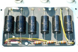 Tavo felt, just from my descriptions via email, that whoever had replaced the capacitors on my Bassman had followed a Blackface paradigm instead of the actual 6G6-B schematic. In amp lingo, he had partially blackfaced my Blonde while doing a cap job. Not cool man! Tavo asked me to take a picture of the filter caps in the filter pan. By the way, for all you non-amp squares, I’m really not making any of these terms up. A few pics later and Tavo was vindicated, or should I say, he was proven right once again.
In the picture above, you can see the filter caps from the ’63 Blonde Bassman as replaced by the previous owner’s amp tech. The work is clean enough, but there are two issues. First, the caps are not what I would call boutique. That’s not an issue unless you’re a tone-chassing snob with more money than brains, so let’s assume that for me, it’s an issue. The second issue, and the root cause of my complaint, is that the left-most pair of caps are larger than the rest of the caps. The physical size was not the issue, but rather the specs of those caps. According to the schematic, all six filter caps should be 20-600 (20 micro-farads [20μF], 600 volts [600V]). Though the four on the right were all 22-500 (acceptably close given the 410V circuit), the left two were 100-350. Apparently, this was what was causing my amp to behave incorrectly.
 Since modern 20-600 capacitors are too physically large to fit in the enclosed pan, amp techs commonly use the slightly smaller 20-500 caps. Since this amp runs at about 410 Volts DC, the 500V caps work just fine. Exposing capacitors to voltage in excess of their rating can cause unpredictable behavior. Actually, the behavior is very predictable – they explode. I ordered up some high-quality Sprague Atom capacitors, including some to replace the other inexpensive caps in the amp, then eagerly awaited their arrival.
While the caps were in transit, I set out to build myself a capacitor discharge tool. Though it may be tempting to work on your own guitar amps, there is one little thing that should keep you from doing so. In fact, that little thing has a lot to do with the capacitors in question. Guitar amps work with high voltage and lots of current. This particular amp idles at 410-420 Volts DC to pin three of the power tubes, and all that power goes through these six caps. Make no mistake – if you don’t know what you’re doing, you can wind up dead working on a guitar amp. That’s not hyperbole – I mean actually dead, as in kids growing up without a father, dead.
That scary voltage not only traverses these capacitors, it can be stored in them. Even with the amp unplugged, these little cylinders can hold enough of a wallop to stop your heart. If you don’t know what you’re doing, don’t even open the amp up. It’s just not worth it.
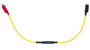 I’m too stupid to listen to such warnings, but I am smart enough to build a tool to help discharge those dangerous caps. I scored a big resister (5-Watt, and between 10k and 100k Ohms), and soldered it up to some spare 12-guage wire. I then shrink-wrapped it all to make it pretty. Before even touching one of these caps, I measured them all repeatedly with my Fluke multimeter. Since I’d left the amp unplugged for a week, they were all drained, so I never needed the tool, but now I have one for next time.
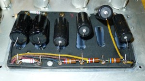 Once the caps came in, I settled in to do the swap. Obsessively checking each cap (did I mention that they can kill?), I clipped the positive connectors and waited for them to pop up, but they never did. It looks like the last guy to work on this amp used either silicon or hot glue to make the caps stick to the eyelet board. While gluing the caps in place can be a good idea, I was not thrilled with the fact that this guy had glued to the caps to the 47-year-old eyelet board. It’s not like this amp is in collectable condition, but I would have preferred a more temporary or reversible modification.
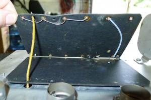 With the old caps removed, I took a look around to familiarize myself with the layout of the filter cap board. This board is actually two boards: the bottom one acts as a nice insulator that separates the solder joints from the chassis, while the top one serves as the connection points for the filter capacitors and all their requisite components. These two boards are only held together by the wires threaded through them, so if you decide to mess with your own amp, take care not to wreck those wires. It’s easy to think that they should just come apart without realizing that you have to desolder a wire to allow the top one to move.
If you’re used to working on modern PCB components, soldering an old tube amp is a pleasure. Everything is so big in comparison with the tiny modern electronics I usually work on. It’s easy to forget that there are connections on the bottom of the eyelet board though. These connections are not obvious from the top, and unless you get every drop of solder out of the eyelets, you may not even know that they’re there. If you remove all the solder, one of these connecting wires might pop out, and then the amp won’t work. In my case, all of these wires were bent in such a way that they all stayed nicely in place.
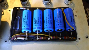 Soldering in the new caps was a challenge at first, mostly because I’m used to working on circuit boards, and not this old-school eyelet stuff. The issue was that the eyelets are only in the top board, so I had to either solder the board in a vertical position so the leads could go through the eyelets unobstructed, or pre-cut the capacitor leads so that they fit perfectly before soldering. I’m not a pre-cut kind of guy, so I did it the hard way. Actually, I’m a do it the hard way kind of guy, so I never even considered trimming those leads to make my life easier.
I patiently soldered in the caps, one by one, making sure that all the wires remained where they needed to be. As I reached for cap number six, I realized that there was no cap number six! With all the prep work I had done, I had somehome only ordered five. Now I’m the kind of guy that if I need six, I order eight, because I like to have an extra in case I break one, or one is bad out of the box. Here I was with only five, when I needed six! To make matters worse, I had ordered extras of all the other parts I needed. Sometimes even I can’t fathom my own stupidity. Since I needed one more cap, I ordered two, and moved on to some other mods.
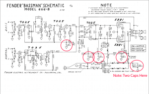
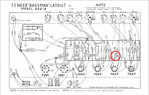 While I waited, I replaced the electrolytic capacitors on the main eyelet board. I also looked into modifying the bass channel on the amp. Tavo had recommended that I pull the capacitor inline with the resister leading to V2. The cap in question is a .002 capacitor inline with a 100k resister that leads to pin six on the second preamp tube. I’ve highlighted this cap in the layout to the right. This capacitor acts as a treble bleed. This serves the same purpose as the treble bleed found in many guitars — to reduce or eliminate some of the treble frequencies.
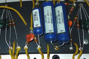 The problem with this little cap is that it chokes all the life out of the bass channel, supposedly to make it better for a bass. This was, after all, supposed to be a bass amp. The Normal channel is coveted by Brian Setzer fans for its wonderful tone, but the Bass channel is largely ignored because it sounds pretty terrible with a guitar. By removing this cap, the amp is supposed to produce some killer tones from the Bass channel as well, especially when playing solid-body electric guitars. That sounded like my kind of mod, so with clippers in hand, I cut that little orange bastard right outta’ there. You can see the before and after gut shots in the two pictures to the right.
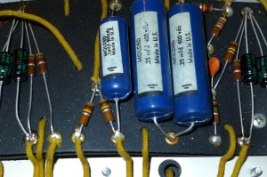 When the remaining capacitors finally came in, I finished up the cap job. I soldered in the remaining filter cap, checked all the connections and solder joints, and ran a thick bead of silicone between each of the caps. The silicone helps to keep them from vibrating against each other at volume. The pan in which these caps sits has a strip of forty five year old foam that holds them down, so I didn’t want to run a bead of silicone over the top of the little blue cans.
With everything soldered back into place, I put the chassis on top of the speaker cabinet, installed the tubes, and fired it up. I’ll admit that I had a fire extinguisher nearby, but I’m proud to say that I didn’t need it. The amp fired right up, nothing exploded, and the tubes didn’t red-plate themselves to a fiery death. I let the amp sit for 15-20 minutes so that it could get to know its new parts. For those who will ask if I used a variac to slowly power up the new caps, the answer is no. I don’t buy into the idea that this needs to be done on modern capacitors.
![]() After it warmed up, I checked out the bias. With the new caps, the voltage to pin three on the power tubes seemed to have dropped from 420VDC to 410VDC. In addition to the voltage change, I also discovered that the bias reading dropped from 35mA to 23mA (as measured on the power tubes with a Euro Tubes bias tool). 70% would be 56mA, and running at less than 50% was just a bit too cold for my tastes. After some more parts and adjustments to the bias, the amp was finally humming along as it was meant to.
After it warmed up, I checked out the bias. With the new caps, the voltage to pin three on the power tubes seemed to have dropped from 420VDC to 410VDC. In addition to the voltage change, I also discovered that the bias reading dropped from 35mA to 23mA (as measured on the power tubes with a Euro Tubes bias tool). 70% would be 56mA, and running at less than 50% was just a bit too cold for my tastes. After some more parts and adjustments to the bias, the amp was finally humming along as it was meant to.
So was all this work worth the effort? Absolutely! Where the amp had been behaving more like a Fender Twin before, it now acted more like a vintage Bassman. The nice, grainy power tube breakup could be heard starting at a volume of about three and a half, and the introduction of the Nocturne Brain Seltzer really kicked it into tone heaven. Finally, my Gretsch SSLVO hollow body guitar sounded like it should through the Normal channel.
The Bass channel modification was a nice bonus too. Where the Bass channel had produced all the tonal variety of a smelly old amp with a wet blanket thrown over it, it now produced a wonderful overdriven sound reminiscent of an old Marshall. My Les Paul and SG sounded absolutely amazing through this channel, as did my Gretsch Billy Bo. I bet whoever had this amp before me sold it off because, even after a cap job, it just never sounded right. That’s a shame, because after putting the right caps in, it sounds divine. Add the newfound versatility of a usable Bass channel, and this amp now delivers the goods in a way I never expected.
Donate: PayPal Crypto:
ETH: 0x0AC57f8e0A49dc06Ed4f7926d169342ec4FCd461
Doge: DFWpLqMr6QF67t4wRzvTtNd8UDwjGTQBGs
“he reason that the two left-most caps didn’t explode with 410 VDC running through them is that they are wired in parallel, and
///
thus double their capacity (2 x 350 = 700 Volts).
///
Wrong. 2×350 volts = 350 volts…. 20 + 20 = 40 mfd.
2 20mfd 350v caps in SERIES = 700v 10mfd but this is not a good thing to do.
Thanks for pointing that out. I’ve removed the offending section of the article.
Bert is wrong! Parallel would double capacitance to 200uf and keep the same 350 voltage rating. In the photo the two 100uf caps look like they are wired in parrallel (dead wrong) which would strain the rectifier and cause the sound to be non bassman. The correct way which the tech was close to would be to wire them in series + – + – which would half the capacitance to 50uf and doubling voltage to 700.
The confusing part is the original 20uf caps were wired in parallel yielding 40uf.
Typo? “her replied that” should be “he replied that”
Nice blog!
The stock setup in many 6G6-Bs, including mine, was 2x70uf @ 350volt in series – for a net of 35uf at 700 volts.
This is basically the same as putting two 20uf in parallel, for a net of 40uf @500 volt. Since the caps are +/- 20%, the actual value could vary considerably.
I prefer the setup that gives you a 700 volt rating on the main set of caps. The modern Sprague Atom equivalent is actually 80 uf @ 450 volt.
In your modified setup, you can remove the 220K resistors shown in your pics. The are meant to equalize voltage across the caps in series, but do nothing for you when the first two caps are in parallel. UNLESS you didn’t change the wiring on the back of the tag board and still have the two operating in series – which would be interesting, as it nets 10uf for the main cap!
JBGRETSCHGUY got it right. And the F & T caps are very good quality and did not need to be changed. If you did not remove the wire underneath the cap board, then the caps are in series and you have 10 uf on the first stage. The most positive result from all your work was the result of removing the shunt cap on the plate resistor. With the 100/350 caps in series, you had 50 uf on the first stage. With the 20’s in parallel, you had 40.
Roy, as can easily be expected, is correct here. The layout pictured in your photo after “restoring” is not correct with those balancing resistors in there. I just did a 6G6B and although B+ is only 465-ish volts you can observe a voltage increase when the amp is in standby on those first 2 capacitors. On the example on my bench it was 485v with the variac at 122vac. Raise this to 124vac and the voltage gets right close to the 500v limit of the first capacitor voltage limit. So although 500v caps seem to be just close enough to being within an acceptable range, muting the amp with the standby switch (or powering up in standby) hit the first filter stage with much higher voltage than when the amp is operating.
I believe the configuration your amp came with looks like the most appropriate way to go as 600v Sprague atoms do not fit under the pan. The question remains – why did you amp not break up the way you wanted it to the way it arrived? If your cap job did not change the modified wiring arrangement that your amp came with from the previous seller then you are indeed running 10uf which should be expected to sag (and possibly have more inter-modulated distortion) than a stock 6G6.
I had a 1963 Bassman and it has a blonde grill. I think the 1962 had the brown grill which is what our lead player had. GREAT sounding amps. Wish I had kept mine.
6G6-B 1963 Bassman amp
Allo Gab
First sorry for my bad Inglish
I need your advise about power output
My mesurement is=
output voltage at 1khz 8 ohm (PWR resistor) at Clipping point is 13 V
So is around 21 Watts !!!!????
It is normal?? 21 Watts
The signal and clipping point are clean
Thank in advance
Claude
–
Maybe it was done that way because the original owner wanted it that way? You’d be surprised at the things people ask amp techs to do. Without knowing the history of the amp tech involved and the owner, ‘not cool!’ is missing the point.
I think the main reason for the tone improvement has something to do with the fact that your bias changed by 30% after only doing a cap job. The bias went down which would normally bring the B+ up, however, it went down too. If you changed a really bad cap in the bias circuit and the reduced the filtration on the power supply that might explain it, but I suspect you may have fixed something by accident, like some bad solder joint?
Hello, are the blue Ajax caps all original or have they been replaced by other identical blue Ajax caps (NOS (NEW OLD STOCK)? I ask this because these blue caps seen in the photo look very new.
Sorry no idea. This article is from 15 years ago and I no longer own that amp.