After Hurricane Sandy, I became slightly obsessed with alternative power, but focused most of my energy on generators, always remembering that I can only store so much gas. The natural alternative to engines and gasoline is solar power, but I wasn’t sure I was looking for a whole-house solution since we don’t have room for batteries and I’m not a fan of selling my surplus energy back to the power company. An idea for a portable solar solution rattled around in my head for years, and while studying for my Amateur Radio Extra Class license exam (K2GAD/AE!), plans started to germinate that resulted in what you see here. I present to you the Internet unveiling of The Yellow Box of Power.
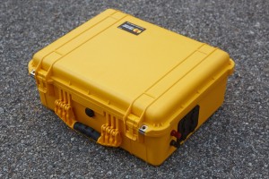
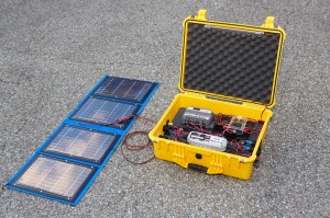
The Yellow Box of Power is a very yellow Pelican box (size 1550) loaded up with 36 amp-hours of 12-volt battery capacity that can be charged by way of normal 120V household power or through one or more solar panels. It is mostly self-contained, is completely portable, will charge laptops and phones, run a ham radio station, or just light up a room. It will even float! Actually, it won’t float for long since I cut a bunch of holes in the side, but it’s pretty darn water resistant. Read on to learn how I made it after a quick rant about the term solar generator.
A box like this (along with a solar panel) is sometimes called a solar generator by companies trying to take your money, but I refuse to use that term because such a device does not exist. You see, a generator is a device that converts mechanical energy to electrical energy (like the one pictured to the right), and the Yellow Box of Power does no such thing. A photovoltaic cell or solar panel converts solar energy into direct current (DC) electricity using semiconducting materials that exhibit the photovoltaic effect (wikipedia). Thus, energy is not being generated, but rather converted. Furthermore the box itself is not a generator, but rather a battery, some chargers, and some fancy wiring in a Pelican box. Still, people may arrive here searching for the term solar generator, so here: solar generator, solar generator, solar generator! End rant.
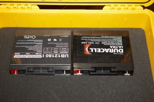
The first requirement for such a project is one or more batteries. I originally started with one 12V 18Ah battery, but decided on two because more is almost always better. By connecting them in parallel, I upped the capacity to 36Ah while keeping the voltage the same. For those not familiar with amp-hours, 36Ah will supply one amp of current for 36 hours. Plugging in my Macbook pro through an inverter pulled about five amps and took about two hours to charge. Thus, I could charge three Macbook Pros (36 / (5×2) = 3.6) and a couple of phones on a full charge. More amp-hours are better, but lead acid batteries are heavy, so I had to balance weight against capacity and cost.
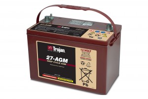
I could have used lithium batteries which would have significantly lowered the total weight, but they were very expensive for the capacities I was interested in. I chose sealed lead-acid (SLA) batteries of the type known as AGM. Without getting too deep into SLA battery technology, I decided that AGM was a better choice for me. My original plan involved a size 27 Trojan AGM battery that was a whopping 99Ah, but the battery itself weighed in at 64 pounds which would have made the whole project weigh in at over 80 pounds and that’s just too heavy. Here’s a tip for you battery hunters: if a battery is bigger than the one in your car and comes with a handle, it’s probably too big for your “portable” project. That battery also had a price tag of almost $300 which was almost more than the rest of the project combined.
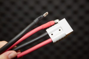
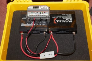
With the batteries in place, I had to wire them together. If there’s a time to be careful during a project like this, it’s when you’re wiring two big high-capacity batteries together! I decided to use 6-gauge welding/battery cable and to add a cutoff mechanism that would split the batteries, thus disabling the entire system. This would allow me to work on the batteries without them being in parallel, thus lowering the risk of death since death can be a bummer. I almost died only once, though that was more from fright than from DC current. Be careful! These are not little 9V cells; batteries of this capacity can kill you dead. I chose 6-gauge wire because the inter-battery link should be able to handle high currents and I chose welding/battery wire because it’s soft and easy to work with. The connector is an Anderson 50A Powerpole commonly used for battery interconnects. Notice the shrink-wrap, which I recommend on every connection. It looks great and adds even more insulation between the electrons and your very conductive fleshy bits.
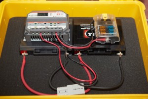
Since the goal of this system was charging via solar power, I needed something called a Solar Charge Controller. The Charge Controller takes in electricity from one or more solar panels, which can vary greatly in both voltage and current based on the amount and angle of sunlight falling on the panel(s), and regulates it so that the battery receives what it wants to see. A good Solar Charge Controller will also prevent the battery from completely draining, charge the battery according to the advanced algorithms that modern batteries require, and even prevent electricity from flowing the wrong way in the system. Though perhaps a bit overkill for my needs, I went with a Morningstar ProStar PS-30M Charge Controller. This I wired to the inside terminals on my batteries using 10 gauge wire. My goal was a 30-amp capacity though the system, which the PS-30M supported. I could have gone with thinner 12-gauge wire, and probably should have for the ease of routing the wire, but I’m a fan of over-building wherever possible.
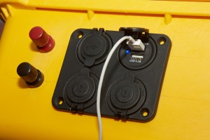
I had envisioned a variety of connections both in and out of the box. These included two 12V inbound ports, an AC inbound port, two 12V outbound ports, four USB ports, and one set of 12V posts. Doing this right meant that each of these circuits should be fused, so I bought a marine fusebox and wired that up to the “load” terminals on the solar controller, thus creating a central point for all outbound power. At this point I realized that I was going to have some issues with my choice of 10-gauge wire because it is very stiff and can be hard to work with. Since nothing is holding these devices down, the wire had to be bent just perfectly for them to stay where I wanted them to be. I ended up rewiring the entire box more than once and used thinner wire as I got towards the various jacks.
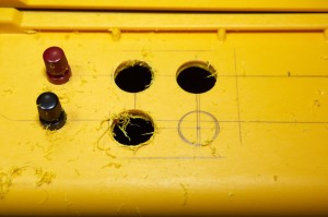
At this point I was ready to wire up some inlets and outlets, so I pulled everything out of the box and got my pencil. I’m great with a soldering iron and wires, but when it comes to drilling holes, I mess it up every damn time. As a result, I don’t measure twice and cut once; I measure 38 times and cut once – and I STILL usually mess it up! I took my time, drew out my planned holes, checked and rechecked, then let loose with the drill. In this picture you can see the two posts already installed and three of the four outlet port holes. Note the mess.
A word about the mess is in order. Drilling into a pelican box (especially a bright yellow one) doesn’t just make a mess, it makes an unholy mess. I had decided to work in my home office (without shoes) where we had just done a pile of construction and the carpet was due to be ripped out. Still, take a look at the yellow plastic curly shavings, because let me tell you, they were everywhere. If you decide to drill into a Pelican box, do yourself a favor and do it outside — in someone else’s yard. Oh, and the resulting holes that caused all that yellow snow is why the box is no longer watertight. You know, in case that wasn’t obvious.
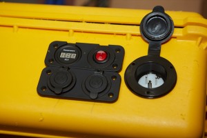
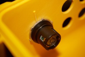
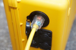
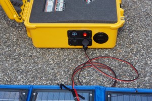
With the holes drilled (and straight – hooray!) I went on to the inlet side and drilled those holes. This side has one large hole for the AC inlet (note the male plug recessed in the port), two 12V power jacks, a volt meter, and an on/off switch. Neither the meter nor the switch were really required, but I thought they were cool and anything with a name like the Yellow Box of Power should be as cool as possible. At this point I just test-fit all the holes. They were nowhere near ready for final installation, mostly because the holes were very rough and I had to further violate the integrity of the mighty Pelican box. Why? I’ll tell you why.
There were two issues. First, the holes were rough and there is yellow plastic bits everywhere including what looks like flash still attached to the hole. When you cut through plastic with a hole saw, it cuts like it would through wood, but it also melts, so many bits don’t break away and have to be sanded off. The second issue was that the Pelican box is built to be very robust, and to that end it includes small ridges inside that help keep the walls rigid. Unfortunately, these ridges prevented the locking nuts from sitting flat against the wall, thus causing the item being mounted to sit funny and not seal against the wall. Not only did I have to sand the holes smooth, I had to chisel these ridges away for about 1/4″ around the circumference of the hole.
This picture shows the AC power inlet washer sitting flush with the wall as a result of me chiseling off the ridge seen in the previous picture.
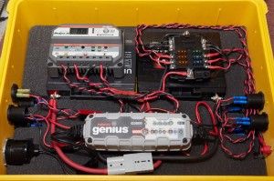
With the holes all smooth and the ridges chiseled off, it was time for one more major device to be installed. In order to charge the batteries with AC power, I needed another charging system since The Solar Charge Controller doesn’t work with AC. After doing some research I discovered that it was perfectly acceptable to have two charging systems wired up so long as the AC charging system was not being controlled in any way by the Solar Charge Controller and vice-versa. I bought a Genius G3500 battery charger and wired it directly to the outside lugs of the battery pair.
It was around this time that I decided that I would connect everything together with Anderson Powerpoles so that I could more easily add/remove items for testing or future expansion. These are handly little connectors that are basically smaller versions of the 50A connector I used on the battery interconnect. Powerpoles are very popular with Ham Radio enthusiasts because they allow easy disconnect capability which is great for events like Field Day or for emergency communication where portability is valued.
With all the holes drilled and all of the inlet and outlet ports installed, I wired up all the circuits using the Powerpoles. I also decided to braid (twist, actually) most of the wires to make them look nice and to keep the circuit leads together which makes them easier to troubleshoot. There’s nothing like a box full of random red and black wires when you’re trying to figure out what’s wrong. At least with them twisted together each circuit is very easy to trace.
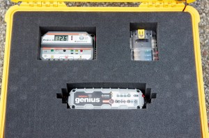
Believe it or not, one of the most difficult parts for me was cutting out the foam. I had a certain idea of what I was trying to accomplish, and I came pretty close to my goal, but if I were to do it again I’d probably screw all of the major components to a piece of acrylic. I actually bought the acrylic to do this, but I didn’t plan ahead well enough in advance and there’s really no easy way for the wire to traverse the upper and lower regions that would would be separated by the acrylic. Still, that’s me being over-analytical. Most people just seem to look and go, “oooh!” What made this process difficult is the fact that much of the foam is cut out underneath but only halfway to the surface. This is to allow the larger routes of wire and the rather large jacks to have space within the foam.
Really, unless you want to see the charge status, there’s no operational reason to open the box. Both chargers will lower the voltage when the batteries are fully charged, so in theory it could just be left plugged in all the time. There is a risk of over-voltage hydrogen production, though this should be minimized by using SLA batteries and the fact that the box is no longer air tight. Still, charging with the box open is the safer option. Risk of explosion is also the reason why I did not permanently mount an AC inverter in the box. With the binding posts, any inverter can be used up to a 30A draw, which is the limit of the box due to the charge controller and the fuse box.
I added an LED wand light that you can see in the next picture that is mounted in the lid of the case so that when it’s open the case itself can light a room, or just light itself. The wand is removable and may be used as a flashlight or work-light.
When charging via solar power, the Solar Charge Controller regulates the voltage and current to the batteries. In this pic, the case is being charged via this CT Solar 32W nylon folding solar panel. You may remember that there are two 12V inlet jacks. If I were to hook up another panel, they would be wired in parallel thanks to how I wired them, thus doubling their current while keeping the voltage the same (assuming the same exposure to the sun). These panels are great because they will produce current on a cloudy day, though they really rock in full sun. I actually have another panel on the way but since I bought them both used on eBay, the second one had not yet arrived when I wrote this article.
The sun isn’t always out, though, and sometimes good old AC mains power is the way to go, and that’s what the Genius charger is for. It takes a good five to six hours to charge the box from AC power, and the Genius G3500 produces 3.5 amps. I’m interested to see how quickly I can charge using the two solar panels because I managed to get 2.5 amps out of just the one in full sun. Of course getting full sun is a challenge even on a clear day because tilting the panels even a couple degrees away from the sun causes the amperage to drop significantly. Could the box be charged by both solar and AC concurrently? Probably, but conflicting charge controllers seems like a bad idea so I’ll probably not risk it.
The Yellow Box of Power was a fun project for me that will be all sorts of useful. Ham Radio Field Days are a natural for a box like this, but the real intent of the box small-time power usage during extended power failures. As I wrote in the beginning of this article, generators are great, but the gas may not last forever.
The only real downsides that I see for this box are the fact that it’s no longer watertight, and that it weighs in excess of fifty pounds which is a bit heavy for my wife and kids, though they could manage it if they had to. Plus, it’s a Pelican box so it would probably survive a fall down the stairs provided it was closed when it fell.
The LED meter and lighted switch both involve parasitic drain which lowers the charging capacity of the panels, but they both consume only 10mA or so. If I find them to be a problem I’ll bypass them. The charge controller also pulls a small amount of current (22mA) for its processor which will slowly drain the batteries over time. If that becomes a problem I could always split the batteries with the quick-disconnect.
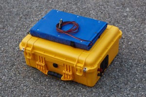
I bought most of the parts on eBay, Amazon.com, and Powerwerx.com which has some very cool stuff if you’re into projects like this. The solar panels are fabulous since they fold up and were designed for for serious expeditions. I’ve been very impressed with the panel’s output and would recommend CTSolar if you’re looking for something similar. I may get another Pelican case to hold the panels and various adapters.
I hope you enjoyed the tour of my Yellow Box of Power. I’d love to hear from you if you’ve built something similar! As for me, I’m now in the odd position of hoping for a power failure to show my wife how smart and well-prepared I am.




wow very kool, im building a power box for usb charging for drones mobile then ac and dc from a car
A Dremel would greatly help in the tooling of the holes in the box. Also, the step drill bits from your favorite hardware store will make nice holes. Both of these methods will produce lots of little plastic bits, so outside is the bet place to do this part of the task.
Excellent idea.
Excellent writeup. I got several good ideas from your effort. Thanks,
Tricks to drilling plastic:
Go slow: Use the slowest speed that you can, and don’t let the drill bit or saw blade heat up. pause frequently.
Keep the work cool: Water cool the work if you can, but be mindful of the possible shock hazard if using line voltage power tools. Definitely use a GFCI (or RCD for the EU folks) when using line voltage power tools around water.
Cordless power tools should be fine, as long as you don’t get the tool too wet.
Use pilot holes: Drill pilot holes for everything, and then work up from there.
Use a hole saw, or a spade or forstner bit for the larger holes.
If you can, start the final hole from both sides. This helps reduce flashing.
I don’t like to encase heat generating devices, such as chargers and charge controllers, in foam, as it reduces the amount of cooling available.
Great write-up. Thank you for taking the time the time to publish a web site to share this information.
I have built four versions of my Go-Kit. Each new version was intended to improve the “Usability” of my kit.
Because my kit is at disaster sites in potentially bad weather, I never put any holes of any kind in the case.
Second, I replaced the Lead Acid internal batteries with LiFeP04 batteries. These batteries weigh less than half the lead acid batteries and HOLD THEIR CHARGE for at least SIX Months and have 5 times the cycle life. In my Go-Kit I have 40Ah. Utilizing the built in Solar charging, my station can run indefinitely at 95% 5%.
95 % monitoring, 5 % Transmiting. http://WWW.emergencyradiogokit.com
Hi GAD!
I ran across this article of yours on the internet. Saved a copy for a project of my own. I hope you don’t mind.
I just picked up an IC 7100. Taking my General next month. Trying to get all of the components together. I’d like to have a system whereby I could have the radio, power supply etc, all in one contained unit (Pelican Box). Something that I could just pull out of the back of the truck and setup as needed, portable. I’d love to hear your thoughts on something like that.
I too live in scenic NJ!
What a beautiful job! Any chance you have a wiring diagram? I’m currently building a battery go-box and am a bit stumped how to provide AC charging AND solar charging to the batteries. I’d also like to have a switch to turn the voltmeter on/off without turning the whole system off. I’m an electronics dweeb!
My box is utilizing a Fat 50 caliber ammo can with 2 12V 20 Ah SLA AGM batteries.
THANK YOU! I am retired military and have pelican boxes I am planning on making into power boxes but other articles leave out things like size of wire that you included. I have two of this size boxes and a handful of little boxes but have been reluctant to start without a little help that you provided. My house has no power out the front where I have a covered deck and I also have a gazebo. I plan on putting in led lighting, two spots for where the barbecue sits to see to cook, a 12v ceiling fan, and of course places to charge phones. I am going to wire it to a central location and then with a copy of your box just plug in. I wanted multiple charging methods so I can take it with me, camping and HAM operations, KL5KH.
Funny, but working a similar project with a yellow pelican case. Biggest difference is that I am using my Noco charger to connect to SAE plugs on the case versus mounting in the case. Gives me more room, less concern over heat, and I still have a battery charger to use around the house. Also was planning a simple disconnect switch to limit the parasitic drain.